Featuring Coreless Element Technology
Flows to 400 gpm (1500 L/min)Pressures to 400 psi (28 bar)
Port sizes: 3" and 4"
The 8340 series filter assemblies are no longer available and are being replaced with Ultipleat® UR629 Filter Assemblies
All replacement filter elements, differential pressure indicators and sealkits remain available for this series. See 'Ordering Information' tab above for details of spares.
Features
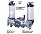
- 8310 or 8314 Assembly (Ultipor® III Element)
- Commuter Valve - Built in Design Requires No External Lines. Use to Equalize Pressure During Element Change
- Duplex Check Valve at Outlet - Seals Off-Line Filter to Prevent Backflow; Simplifies Element Change
- Ball Type Open Center Transfer Valve - Ensures Continuous Filtration While Changing Elements Without Shutting Down the Machine
Maximum Acceptable Working Pressure:
400 psi (28 bar)Fatigue Pressure Rating:
(NFPA/T2.6.1-1974 category 2/90)330 psi (23 bar)
Typical Burst Pressure:
2100 psi (145 bar)Temperature Range:
Nitrile seals -45°F to 225°F (-43°C to 107°C)Fluorocarbon seals -20°F to 250°F (-29°C to 120°C)
140°F (60°C) maximum in HWCF or water-glycol fluids
Dry Weights:
| 8340/8370: | U length–165 lbs. (75 kg) |
| X length– 260 lbs. (118 kg) | |
| 8342/8372: | X length– 475 lbs. (215 kg) |
| 8343/8373: | X length– 680 lbs. (310 kg) |
| 8344/8374: | X length– 890 lbs. (405 kg) |
Filter Element Collapse Pressure:
8310–100 psid (7 bar)8314–150 psid (10 bar)
Materials of Construction:
Head, cover, handle, tube, manifold and valve bodies – aluminum alloy.Center post, core, and internal valve parts – coated carbon steel.
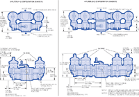
Dimensional Drawings

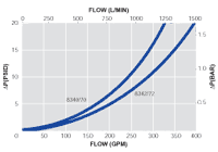
| Figure 1. Housing Pressure Drop using fluid with 0.9 S.G. Housing Pressure drop is directly proportional to specific gravity. |
 |
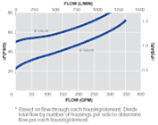
| Figure 2. Bypass Valve Pressure Drop using fluid with 0.9 S.G. Bypass valve pressure drops are directly proportional to specific gravity. |
 |
Element Pressure Drop Factor*
Multiply actual flow rate times factor to determine pressure drop with fluid at 150 SUS (32 cSt), 0.9 S.G.Correct for other viscosities by multiplying new viscosity in SUS/150 x new S.G/0.9.
8310/14 Series Element  P factor (psid/gpm) P factor (psid/gpm) | |||||
| Length | KZ | KP | KN | KS | KT |
|---|---|---|---|---|---|
| 16" | 0.089 | 0.047 | 0.040 | 0.031 | 0.022 |
| 39" | 0.034 | 0.018 | 0.015 | 0.012 | 0.008 |
* Based on flow through each housing/element. Divide total flow by number of housings per side to determine flow per each housing/element.
| |||||
Housings, Vessels, or Assemblies
| Assembly P/N: | H |
| 83 |
|
|
|
|
|
|
|
|
|
|
| Table1 |
| Table2 | Table3 | Table4 | Table5 | Table6 | Table7 | Table8 |
| Element P/N: | HC 83 |
| F |
|
|
|
|
|
|
|
|
|
| Table2 | Table5 | Table6 | Table1 |
|
|
|
Note: Choose from the options in the following tables to compile the specific Product Number.
| TABLE 1: SEAL OPTIONS | |
| Code | Seals |
|---|---|
| H | Nitrile |
| Z | Fluorocarbon |
| TABLE 2: ELEMENT OPTIONS | ||
| Assembly Code | Element Code* | Description |
|---|---|---|
| 4 | 10 | Conventional |
| 7 | 14 | Coreless |
*Nominal length in inches. Use code in second column for element part no. | ||
| TABLE 3: QUANTITY OF HOUSINGS | |
| Code | Description |
|---|---|
| 0 | 2 Housings (1/side) |
| 2 | 4 Housings (2/side) |
| 3 | 6 Housings (3/side) |
| 4 | 8 Housings (4/side) |
| TABLE 4: PORT SIZE OPTIONS | |
| Code | Size |
|---|---|
| D48 | 3" flange SAE J518c-Code 61 |
| D64 | 4" flange SAE J518c-Code 61 |
| TABLE 5: FILTER ELEMENT OPTIONS | ||
| Code | ßx  200 200 | ßx(c)=1000 |
|---|---|---|
| KZ | <1 | 2.5 |
| KP | 3 | 5 |
| KN | 6 | 7 |
| KS | 12 | 12 |
| KT | 25 | 22 |
| TABLE 6: LENGTH OPTIONS* | |
| Assembly Code | Element Code** |
|---|---|
| U | 16 |
| X | 39 |
* Use code in second column for element part no. | |
| TABLE 7: BYPASS VALVE OPTIONS | |
| Code | Description |
|---|---|
| A | 25 psid |
| B | 50 psid |
| Y | Non-bypass with 16 psid indicator |
| N | Non-bypass with 35 psid indicator |
| TABLE 8: DIFFERENTIAL PRESSURE DEVICE OPTIONS | |
| Code | Description |
|---|---|
| P | Visual indicator with thermal lockout |
| D | Visual indicator with no thermal lockout |
| L | Electrical switch (SPDT) with 6" leads |
| T | Electrical switch with DIN connector |
| M | 'T' type switch with matching wiring cap |
| S | Electrical switch with MS receptacle |
| V | Combined visual/electrical with DIN connector |
| B | Plug
in place of indicator |
| 2 | 'P' and 'L' |
| 3 | 'P' and 'S' |
Earn 10% off* your next order online by leaving a review of this product. Please login to your account to leave a review. We appreciate and value your feedback.
*Subject to Terms and Conditions.


