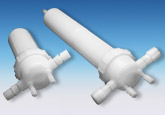
PFA single cartridge filter housing for critical chemical applications in electronics
- High purity 100% fluoro-polymer construction
- All wetted parts are fluoro-polymers (PVDF non-wetted)
- Stationary bowl with rotating locking ring ensures positive closure seal and easy filter replacement
- Designed for higher temperature and pressure applications
- Choice of two filter inlet/outlet configurations for easy installation
- Packaged in a cleanroom environment
- Full 1 in. / 25 mm inlet/outlet ports for increased flow available in 10 in. / 254 mm, 20 in. / 508 mm and 30 in. / 762 mm
Materials of Construction
- Housing: High purity PFA head, bowl and plugs
- O-ring: FEP encapsulated fluoroelastomer
- Locking Ring: PVDF (non-wetted part)
Connections
- Inlet / Outlet:
- 3⁄4 in. or 1 in. flare
- Flowell1
- Pillar2
- 3⁄4 in. or 1 in. butt weld pipe
- Vent and Drain:
- 1⁄4 in. flare
- 3⁄8 in. flare
- 1⁄4 in. butt weld pipe
- 1⁄4 in. female NPT
- 1⁄4 in. closed end
- Cartridge Connection: Double 222 O-ring
Operating Conditions
- Maximum Operating Pressure
- 50 psig @ 194 °F / 3.4 bar @ 90 °C
- 100 psig @ 77 °F / 6.9 bar @ 25 °C
1 Flowell is a product of Flowell Co., Ltd.
2 Pillar Fitting is a trademark of Nippon Pillar Packing Co., Ltd.
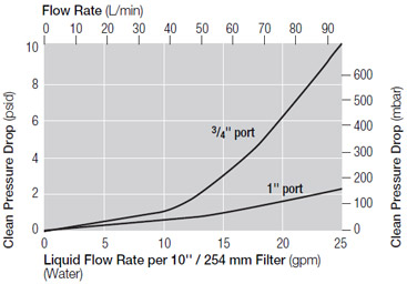
Pressure Drop vs. Liquid Flow Rate3

3 For liquids other than water, multiply the pressure drop by the specific gravity of the fluid. Pressure drop curve represents an empty housing.
Housings, Vessels, or Assemblies
Dimensions

Dimensional Data
| Description | Housing Style | Length (L) (in. / mm) | Width (W) (in. / mm) | ||
| T | S | T | S | ||
| Fluoro-Plus II PFA 10 in. / 254 mm housing with: | 3⁄4 in. Butt weld pipe fitting | 16.0 / 406 | 17.3 / 439 | 9.0 / 229 | 5.9 / 150 |
| 3⁄4 in. Flare style fitting | 19.5 / 495 | 16.3 / 414 | 10.5 / 267 | 5.9 / 150 | |
| 1 in. Butt weld pipe fitting | 16.0 / 406 | 14.3 / 363 | 9.0 / 229 | 5.9 / 150 | |
| 1 in. Flare style fitting | 19.5 / 495 | 16.3 / 414 | 11.0 / 279 | 5.9 / 150 | |
| Fluoro-Plus II PFA 20 in. / 508 mm housing with: | 3⁄4 in. Butt weld pipe fitting | 25.7 / 653 | 9.0 / 229 | ||
| 3⁄4 in. Flare style fitting | 29.3 / 744 | 10.5 / 267 | |||
| 1 in. Butt weld pipe fitting | 25.7 / 653 | 9.0 / 229 | |||
| 1 in. Flare style fitting | 29.3 / 744 | 11.0 / 279 | |||
| Fluoro-Plus II PFA 30 in. / 762 mm housing with: | 3⁄4 in. Butt weld pipe fitting | 35.5 / 902 | 9.0 / 229 | ||
| 3⁄4 in. Flare style fitting | 39.1 / 993 | 10.5 / 267 | |||
| 1 in. Butt weld pipe fitting | 35.5 / 902 | 9.0 / 229 | |||
| 1 in. Flare style fitting | 39.1 / 993 | 11.0 / 279 | |||
This information is a guide to the part number structure and possible options. For availability of specific options and housing details, please contact Pall.
Example Part Number: FP T 20 3⁄4 FW 3⁄8 FLC ( See bold references in tables below)
Part Number:
FP < End Configuration Code from Table 1 > < Length Code from Table 2 > < Inlet/Outlet Size Code from Table 3 > < Inlet/Outlet Style Code from Table 4 > < Vent/Drain Size Code from Table 5 > < Vent/Drain Style Code from Table 6 >
Table 1 - End Configurations
| Code | End Configurations |
| T | T-style |
| S | Straight (in-line) |
Table 2 - Lengths
| Code | Lengths |
| 10 | 10 in. bowl |
| 20 | 20 in. bowl (T-style only) |
| 30 | 30 in. bowl (T-style only) |
Table 3 - Inlet/Outlet Sizes
| Code | Inlet/Outlet Sizes |
| 3⁄4 | 3⁄4 in. |
| 1 | 1 in. |
Table 4 - Inlet/Outlet Styles
| Code | Inlet/Outlet Styles |
| BW | Butt weld |
| FL | Flare |
| FG | 1 in. Flange (T-style only) |
| FW | Flowell |
| PL | Pillar style fittings |
| FLC | Flare cap installed |
Table 5 - Vent/Drain Sizes
| Code | Vent/Drain Sizes |
| 1⁄4 | 1⁄4 in. |
| 3⁄8 | 3⁄8 in. (Flare only) |
Table 6 - Vent/Drain Styles
| Code | Vent/Drain Styles |
| BW | Butt weld |
| FL | Flare |
| CE | Closed end |
| FP | Female pipe thread |
| FW | Flowell |
| PL | Pillar style fittings |
| FLC | Flare cap installed |
| Part Number | |
| ACS0655AA | Spanner wrench |
| T8316030 | Mounting clamp and bolt assembly |
Earn 10% off* your next order online by leaving a review of this product. Please login to your account to leave a review. We appreciate and value your feedback.
*Subject to Terms and Conditions.


